Tuesday, February 23, 2010

EEE Car Charger

I have an Eee 701 that I find extremely practical to have around. About a week ago I needed a car charger for the machine, and decided to buy one. There doesn't seem to be much choice in the matter. You either go with Asus's $50+ thing or get a chinese one. I got a chinese one, which lasted all of 30 minutes. It got extremely hot, then blew the fuse. I replaced it with a new one, which it immediately blew out as well. When I got home after some considerable trouble I took the damn thing apart (It was partly glued, yay.) and was staring down at a switch-mode DC DC converter.
I tried replacing pretty much every component besides the PWM controller chip but it still kept blowing the fuse.

I gave up shortly afterward and decided to build a PSU myself. I wanted to use things I had on hand so I went with the MAX668 that I used in the Laptop powered from SLA project. This is a Step-Up converter but it supports a SEPIC topology which would make it work in both Step-Up and Step-Down modes.

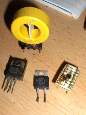
I designed the board, carefully hand-wound the SEPIC dual-power inductor, soldered it all together


And failed miserably in my attempts to get it working right.

I've tried 3 different FETs, 5 different inductors (both dual windings and separate cores), 4 different filter cap configurations, 3 different SEPIC coupling capacitors and 3 different Schottky diodes. I've replaced ALL of the components at least three times, yet my best result was an over 4Volt drop with a 2 Amp load. To sum it up in one word "Useless". At this point I wasted 2 days trying to track down the problem. I've compared the board layout to the schematic, and the schematic to example designs about a dozen times and I couldn't find the reason for the drop. I was not ready to waste any more time on it.

Determined to not waste more money either, especially on a chinese charger that might last under an hour again I asked around and managed to get a UA78HGASC part. This blast from the past is an adjustable 5 Amp Low-Drop-Out Linear Regulator in the TO-3 package. I've seen it mentioned in hobby electronics publications from 1987. From what I understand it's also a relatively rare part.


For anyone who'd slam this because LDOs are inefficient consider the following.
According to this LDO efficiency equation:
% Efficiency = [(VOUT) / (VIN)] * 100
The efficiency of this circuit, if we use 13V for Vin (as a voltage average for SLA) and 9.8V for Vout, is around 75%.
Theoretically a 90% efficiency can be achieved with switching regulators. A measured efficiency of around 80% was achieved by the good people who've come up with the reference designs for MAX668 SEPIC configurations. (The efficiency also declines as the load increases, but let's not think about that) So around 80% using Ultra Low RDS-On FETs, Ultra-Low ESR capacitors and taking all board design rules and recommendations into account. I have neither of those custom components, and buying them would cost more than a chinese car charger. Not to mention that I can't even BUY the kinds of ceramic caps that most of the reference designs require. It is because of this that I probably can't achieve efficiency even close to 80% with a home-built switching regulator. BUT let's say I did. Even then is 5% worth all the extra trouble/time/components?

So back to the LDO.
I had the perfect project box for this. The heat sink fit perfectly on top of it. I soldered it all together. It only needs 2 small caps and 2 resistors, as opposed to all the things a switching circuit does. I just put those on a piece of stripboard. Set the voltage. Did a load test at 50Watts. Voltage Drop.. 0.06 Volts. Things were looking great. I plug it in and... the Eee doesn't charge.
At this point I was close to setting both attempts and the Chinese charger on fire but on a whim I measured the voltage on the SLA battery I was using for testing and I got 14 Volts. Wait.. what? 14Volts is too much even for a fully charged AGM SLA, and this one was nowhere near fully charged.

So after the inevitable realization that my multimeter is measuring around 1.5volts more than the actual voltage of things because it's battery was dead, and raising the output voltage of the regulator accordingly the Eee gave in and started charging like it should. Finally.. after several days I had a car-charger. I don't know about other laptops or netbooks but the Eee 701s can run off their chargers with the battery removed. This also effectively turns this charger into a way to run the Eee off an SLA battery directly.

I feel that I should add a little bit of info on the Eee charging voltage.
On the sticker, and on the AC charger it says 9.5V @ 2.135A.
This is wrong. In fact something around 9.8 is preferred, and that's still 0.2Volts LESS than the AC charger outputs while running the Eee directly off it, without a battery.
Other people have also confirmed that their AC chargers drop only to around 9.8 - 10 Volts while powering the Eee. In fact, it seems like anything below 9.8 is insufficient (Eee shuts down, charging led blinks on-off). Best way to make sure is to measure the charger voltage while running the machine off it. YMMV but 9.8 worked out perfectly for me.

The end result:


Monday, February 1, 2010

Water Pipe Anti-Freeze Heating

UPDATE:

Check out V2 of this project here. Simpler and much less overkill :)


We have 2 buildings on our property: the house and an office building. Between the two is a semi-open garage. Through this garage runs the water pipe to the office building which is exposed to outside temperatures.
The usual procedure for this pipe during winter was to completely drain and disconnect it so that it doesn't freeze in. This has become somewhat of a pain as I needed the water during winter so solving this has become a project of mine.
I managed to acquire a bit of heating cable that I could run in pair along the length of the pipe.
One "channel" at 12volts came out to about 47ish Watts for the entire length of the cable.
I wasn't sure at first if this would suffice, but I gave it a try. The heating cable was taped to the underside of the pipe with PVC tape and copper tape where I assumed it would matter (I would've done it with copper tape along the entire length but it's expensive :) ) The pipe was then covered in foam insulation.


A DS1621 temp. probe was installed (marked with yellow tape on the picture) on the top of the pipe. (The heating cable running at the bottom should ensure that the probe isn't being heated directly by the cable, which would make measurements useless.)
Both the cable for the probe and the heating cable go into the boiler room that is accessible from the garage.
I designed a controller from what I had on hand. An old ATX PSU and an ATMega8(overkill). The AtMega is powered by the standby voltage of the PSU (5VSB). PSON is connected to PORTB.0 so the AtMega can switch the ATX PSU ON or OFF depending on temperature. (The PSU turns on when PSON is pulled low). The heating cables are hooked up to a 4pin Molex Connector.

I admit I didn't make exact measurements of the pipe temperature with the heating on, but the day after I finished this project we had -16 degrees Celsius and the pipe didn't freeze in. Good enough test for me, as we didn't have anything colder in the past 10 years. The controller sits on top of the ATX psu
in a cheap electrical box. 2 LEDs were installed, one shows that there's standby voltage, the other is a heating status / error led.


I use only 1 channel for now, since it seems to have been enough to keep the pipe from freezing in at -16C. The other channel is used as a load for the 5v rail of the PSU (at 5V it doesn't provide much in terms of heating) As it turns out, the 5V rail has to be loaded to stabilize the 12V rail, otherwise there will be huge voltage drop.

The DS1621 was actually a thermostat IC and I was considering using it in a standalone configuration but sadly that can't be done as the thermostat
functionality doesn't start until a "Start Convert" command is sent to the chip through I2c. That meant a microcontroller was mandatory, so instead of
relying on the internal functionality of the chip I just implemented the thermostat function in code. This also meant I only had to run 4 wires from the
temp probe instead of 5, and I had 4 wire telephone cable lying around.

One could use an Arduino for this, or any other dev board. Since I had an ATmega8 lying around, and my 2051 programmer was out of commission I used that. If I need the Mega8 in the future I'll probably end up replacing the controller with a 2051.

Update Feb. 01:

A few days ago I noticed some weirdness while running the tap, so I checked on the controller. The LED was flashing meaning there was an error condition, and the heating was off. The pipe was beginning to freeze in. There were 2 possible places in the code that could produce that. Either the temp. probe didn't respond or a measurement returned a value greater than 25C (which would be a bad measurement as temperatures were mostly sub-zero that day). It was probably a random hiccup as it continued to work fine after a power cycle. This however convinced me that the code needed to be more resilient. So now it retries if the temp. probe doesn't answer or if the measurement is out of bounds. Only after 3 subsequent failures does it go into the error condition. I also added a speaker that beeps out an error code if that happens, making it easier to notice. I took a picture of the controller after I reflashed it with the new version. It has become somewhat of wiring chaos, especially now that the speaker was added. The board design is a modification of this project. I didn't intend to use it here. It just happened to be the easiest solution at the time.


And the speaker on a strip of mounting tape:


You can find the controller code here. (BASCOM/AVR)


SATA Power Switch

There is a useful project at this site that I duplicated. It's a switch that selects between 2 SATA HDDs (it switches power between two SATA power connectors so that only 1 is active).
It's great for testing alternative operating systems or having a quick-boot surfing system on one hdd and a work related system on the other for example.

The build process is pretty much outlined on the site. Here's how mine looks using a big old 2 deck rotary switch


I had to saw quite a bit off the shaft and spraypaint the knob for it look passable. This is how it looked beforehand:


Chromium Silver: UI Tweaks for Chromium

I believe browser UI should be all about choice, as there is no singular solution that will fit everyone's needs. Power users will usually have their own preferences and tend to set up their browsers a specific way to suit their needs, and allow for more comfortable use. This is something that is sadly lacking in Chrome / Chromium. Even in my FireFox session I have completely customized tab handling, installed an extension to remove unified navigation buttons, (that Mozilla thought each and every one of the their users will like, and decided not to include a disable setting in about:config for), and another one to disable the newfangled location bar, that I found to be pretty useless as well. With 45-55 thousand downloads for each of those extensions there are obviously quite a few people around who agree with me on this matter. These numbers may be relatively small compared to the entire browser user-base, but ignoring the preferences of 50 thousand users may not be that wise of a choice either. On the other hand there are probably users who've come to like these new features and this is fine. It's exactly why users should be allowed to enable/disable features that impact user experience, and customize behavior as they like. Doing this should not be seen as the inability of the UI designer to create the "Perfect UI" (there is no such thing), as this Chromium blog entry seems to imply.

Chromium, by default has close buttons on every tab, unless the tabs reach a certain minimum width, then the buttons are removed except from the active tab. The user can't change anything on this behavior, however for me on-tab close buttons are an irritating annoyance. The first thing I do in FireFox if I set up a new session is disable them. Not being able to do so in Chromium, was really frustrating. I've asked around and for example, a friend of mine prefers on-hover close buttons, and another likes it the way it is. It seems people like different things! Pretty shocking... :) So I've decided to pull a Chromium source tree, add some tweaks and recompile. The end result is what I named Silver tweaks. This allows users to
  • enable/disable the new tab button
  • enable/disable an FF-style close tab button at the end of the tabstrip
  • customize tab close button behavior
  • customize "Open Link in New Tab" behavior
Tab close button behavior options are:
  • default Chromium (as explained above)
  • close buttons on every tab, always
  • no close buttons on tabs, ever (my preference)
  • close button on active tab only
  • no close buttons unless hovering over tab with the mouse
Another thing is when you choose "Open Link in New Tab" in Chromium, it will insert a new tab after the current one. I also found this to be really irritating, as I tend to have blocks of tabs that I don't wish to alter, at the front of my tab strip, one being my RSS reader, and I'm used to opening links from there at the end of tab strip, so I've also added an option to change this.

"Open Link in New Tab" placement options:
  • default Chromium (insert after originating tab)
  • add at end of tab strip
This should cover a wide range of preferences, and make using the browser a lot more comfortable, for "nitpicky" people like me.
Configuring the tweaks isn't really user-friendly (you need to edit a file with notepad) and I don't really intend to change that myself, but please feel free to, I've included my source patches inside the archive.

The settings used for the screenshot at the top are:

"silver": {
"close_tab_button": true,
"link_new_tab_autoactivate": false,
"link_new_tab_place": 1,
"new_tab_button": false,
"tab_behaviour": 1,
"tab_grouping": false
}

After unpacking please actually READ readme.txt, otherwise you won't find where to change the settings :) !! Everything's in the readme !!

Last stable build: --> DOWNLOAD <--

Updates:

Project Abandoned as of May 2011. Moved back to FireFox a couple of months ago. Haven't regretted it.

Nov 28 2010 : Updated patches for current git pull. Did not test anything besides the settings I use. No binary release. Patch can be downloaded here

Feb 4.: Build based on a Feb 4 pull. Found out that a patch on Jan16th that was later thrown out of WebKit fixed a crash bug. Reintroduced the pertinent part of said patch to the build. (or more simply put.. commented out a line) with that, the build seems rock solid. Link updated.


Feb 1.: Rebuilt from a GIT pull on Feb 1st, fixed closetab button jumping around in certain conditions. Link NOT updated. Build NOT as stable as previous one. Link for testing is here.
Jan 17.: Rebuilt from a GIT pull on Jan 16th, Main link is for this release. (Build solid and stable on XP) (link)
Aug 9. : Rebuilt from SVN 22737, link updated (I see some speed improvement in this build) (link for this older release)
Aug 2. : Added new-tab autofocus setting, rebuilt from SVN 22243, link updated


If you found this useful, please leave a comment.

Chromium Silver now uses the default Chromium theme due to general laziness.